In-depth guide to full wave rectifier What is single phase full wave controlled rectifier? working, circuit What is full wave rectifier circuit diagram working advantages full wave rectifier circuit diagram and working
full wave rectification diagram - Wiring Diagram and Schematics
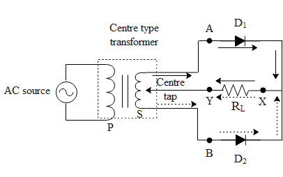
Full wave rectification diagram Full wave rectification diagram Rectifier circuit diagram
In-depth guide to full wave rectifier
With neat circuit diagram and waveforms explain the operation of fullFull wave bridge rectifier circuit diagram Full wave rectifier circuit diagram in multisimHalf wave & full wave rectifier: working principle, circuit diagram.
What is single phase full wave controlled rectifier? working, circuitFull wave rectifier circuit working and theory Draw the circuit diagram of a full wave rectifier briefly explain itsFull wave rectifier basics, circuit, working & applications.
![What is Single Phase Full Wave Controlled Rectifier? Working, Circuit](https://i2.wp.com/electricalworkbook.com/wp-content/uploads/2022/10/What-is-Single-Phase-Full-Wave-Controlled-Rectifier-Working-Circuit-Diagram-Waveform-768x422.png)
Full wave rectifier: working principle, diagram, and formula
Rectifier transformer tapped output waveform inputWhat is single phase full wave controlled rectifier? working, circuit Explain full wave bridge rectifier with diagram pcb designsRectifier circuit diagram.
Rectifier waveformFull wave bridge rectifier – circuit diagram and working principle 4df Half wave & full wave rectifier: working principle, circuit diagram.
![Full Wave Bridge Rectifier – Circuit Diagram And Working Principle 4DF](https://i2.wp.com/www.electroduino.com/wp-content/uploads/2021/04/What-is-Half-Wave-Rectifier-Working-Principle-Circuit-Diagram-Waveforms.jpg)
![What is Single Phase Full Wave Controlled Rectifier? Working, Circuit](https://i2.wp.com/electricalworkbook.com/wp-content/uploads/2022/10/What-is-Single-Phase-Full-Wave-Controlled-Rectifier-Working-Circuit-Diagram-Waveform-1024x563.png)
![Explain Full Wave Bridge Rectifier With Diagram Pcb Designs - Riset](https://i2.wp.com/www.electroduino.com/wp-content/uploads/2021/04/Full-Wave-Bridge-Rectifier-–-Circuit-Diagram-and-Working-Principle.jpg)
![Full Wave Rectifier Circuit Working And Theory - Riset](https://i2.wp.com/www.elprocus.com/wp-content/uploads/2015/01/21.jpg)
![full wave rectification diagram - Wiring Diagram and Schematics](https://i2.wp.com/www.electroduino.com/wp-content/uploads/2021/04/What-is-Full-Wave-Rectifier-Working-Principle-Circuit-Diagram-Waveforms.jpg)
![In-Depth Guide to Full Wave Rectifier - Circuit Diagram, Waveform](https://i2.wp.com/www.tutoroot.com/blog/wp-content/uploads/2023/03/e2.png)
![Half Wave & Full Wave Rectifier: Working Principle, Circuit Diagram](https://i2.wp.com/electricala2z.com/wp-content/uploads/2018/08/Figure-3-6.jpg)
![Draw the circuit diagram of a full wave rectifier Briefly explain its](https://i2.wp.com/www.vedantu.com/question-sets/69a45f3a-74bb-4e58-bc55-f923ddf329963699996288789239680.png)
![Rectifier Circuit Diagram | Half Wave, Full Wave, Bridge - ETechnoG](https://1.bp.blogspot.com/-ph3wPcxTMhg/YO60L9F14dI/AAAAAAAABM0/svLo3j9BnrEtn4_4Ldv94ZgxqVJXvAE7ACLcBGAsYHQ/s1035/Center%2BTap%2BFull%2BWave%2BRectifier%2BCircuit%2BDiagram.png)
![Rectifier Circuit Diagram | Half Wave, Full Wave, Bridge - ETechnoG](https://1.bp.blogspot.com/-bTCLeh50vOE/YO6z8d2H3zI/AAAAAAAABMs/w7vO2Gw8nTcJVMMKq1r3cBeyP8caaUywwCLcBGAsYHQ/s16000/Half%2BWave%2BRectifier%2BCircuit%2BDiagram.png)
![full wave rectification diagram - Wiring Diagram and Schematics](https://i2.wp.com/circuitglobe.com/wp-content/uploads/2015/12/HALF-WAVE-AND-FULL-WAVE-RECTIFIER-FIG-1-compressor.jpg)