Full wave rectification diagram Full-wave rectifier circuit with resistive load. Half wave & full wave rectifier full wave rectifier with filter circuit diagram
full wave rectification diagram - Wiring Diagram and Schematics
Ac rectifier circuit diagram Half wave full wave and bridge rectifier diagram Bridge rectifier circuit diagram
With neat circuit diagram and waveforms explain the operation of full
Full wave rectifier graphCircuit diagram of rectifier Rectifier wave circuit full filter without bridge diagram capacitor tapped diodes center circuits type four electronic board using circuitdigest twoWave rectifier circuit diagram half full voltage output working filter effect principle figure when electronics.
Wave half rectifier capacitor filter circuit diagram output full waveform rectifiers bridge diode using transformer rc resistor operation working diodesCircuit diagram of full wave bridge rectifier with capacitor filter Circuit diagram of full wave bridge rectifier with capacitor filterCircuit diagram of full wave bridge rectifier with capacitor filter.
![Half Wave & Full Wave Rectifier | Working Principle | Circuit Diagram](https://i2.wp.com/electricalacademia.com/wp-content/uploads/2018/11/16-2.jpg)
What is full wave rectifier circuit diagram working advantages
Draw the circuit diagram of a full wave rectifier and explain itsFull wave diagram Full wave rectifier circuit working and theoryFull wave rectifier circuit diagram (center tapped & bridge rectifier).
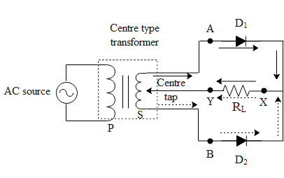
Draw the circuit diagram of a full wave centre tap rectifier with rlIn-depth guide to full wave rectifier Bridge rectifier with filter circuit diagramBridge rectifier circuit diagram with filter.
![Draw The Circuit Diagram Of A Full Wave Centre Tap Rectifier With Rl](https://i2.wp.com/www.physics-and-radio-electronics.com/electronic-devices-and-circuits/rectifier/images/fullwaverectifierwithcapacitorfilter.png)
Function of bridge rectifier cheaper than retail price> buy clothing
Half wave rectifier circuit with diagramCenter tapped full wave rectifier circuit diagram Circuit diagram of full wave bridge rectifier with capacitor filterRectifier rl draw tapped circuits physics.
[diagram] wiring diagram for rectifier and capacitorFull wave rectifier circuit diagram in multisim .
![Full Wave Rectifier Graph](https://i2.wp.com/www.vedantu.com/question-sets/69a45f3a-74bb-4e58-bc55-f923ddf329963699996288789239680.png)
![full wave rectification diagram - Wiring Diagram and Schematics](https://i2.wp.com/electronicscoach.com/wp-content/uploads/2017/08/Center-tap-full-wave-rectifier.jpg)
![Ac Rectifier Circuit Diagram](https://1.bp.blogspot.com/-NLikSO8goCQ/XsuVmIxdbGI/AAAAAAAAC40/DtPRAneVEIsh1lkv2vjdhUcYMRHdbJehwCLcBGAsYHQ/s1600/Rectifier-Page-6.jpg)
![Circuit Diagram Of Rectifier](https://i2.wp.com/circuitglobe.com/wp-content/uploads/2015/12/HALF-WAVE-AND-FULL-WAVE-RECTIFIER-FIG-1-compressor.jpg)
![What Is Full Wave Rectifier Circuit Diagram Working Advantages - Riset](https://i2.wp.com/circuitglobe.com/wp-content/uploads/2015/12/CENTER-TAPPED-FULL-WAVE-RECTIFIER-FIG-1-compressor.jpg)
![circuit diagram of full wave bridge rectifier with capacitor filter](https://i2.wp.com/www.circuitstoday.com/wp-content/uploads/2009/08/bridge_rectifier_with_capacitor_filter.jpg)
![Bridge Rectifier With Filter Circuit Diagram](https://1.bp.blogspot.com/-bTCLeh50vOE/YO6z8d2H3zI/AAAAAAAABMs/w7vO2Gw8nTcJVMMKq1r3cBeyP8caaUywwCLcBGAsYHQ/s16000/Half%2BWave%2BRectifier%2BCircuit%2BDiagram.png)
![Draw the circuit diagram of a full wave rectifier and explain its](https://i2.wp.com/df0b18phdhzpx.cloudfront.net/ckeditor_assets/pictures/1700195/original_6.png)
![Full-wave rectifier circuit with resistive load. | Download Scientific](https://i2.wp.com/www.researchgate.net/publication/3050415/figure/fig1/AS:633224116060161@1527983802709/Full-wave-rectifier-circuit-with-resistive-load.png)
![Bridge Rectifier Circuit Diagram With Filter](https://i2.wp.com/www.physics-and-radio-electronics.com/electronic-devices-and-circuits/rectifier/images/bridgerectifierwithfilter.png)